Designing critical fluid control systems for space launch vehicles requires a deep understanding of the performance of the components under the most challenging conditions. A launch vehicle experiences huge shocks, vibrations and constantly changing forces during the flight to deliver its payload. All fluid control components and systems involved in the performance of the rocket must be designed and tested to assure their reliable operation during the entire flight. For the most critical systems, it is imperative to design in redundancy in the event of a component failure to ensure the success of the mission. The project engineer and supporting design team must take all of this into account, while keeping the system as light and small as possible.
A major space Launch Vehicle (LV) supplier teamed up with Valcor Engineering to upgrade the performance of an existing system that uses multiple single, direct acting solenoid valves to control the flow of propellant to the rocket motor. The customer was on a tight schedule to design and implement the new system, adding to the challenge of taking on the project.
The LV customer provided a short list of specification for the new systems:
- High flow
- High pressure
- Simple on/off control
- Minimum low flow
- 3 parallel flow paths
- Replaceable drop-in orifices for custom flow control
- An interchangeable system compatible with gaseous oxygen and other gaseous propellants
These systems typically control gaseous nitrogen (GN2) and gaseous oxygen (GOX). In some cases, the systems will also control other gaseous propellants.
Working with the specifications above, Valcor recommended the use of pilot-operated solenoid valves for the high flow valves and replacing the many individual direct acting solenoid valves with a custom designed, fully integrated valve manifold. A common inlet manifold distributes the propellant push gas and diverts a small amount of each gas for use as the pilot pressure in operating the high flow valves. The pilot pressure for the high flow valves is vented to an area downstream of the manifolds where it does not affect the system’s operation. The result was a custom propellant pressurization manifold system.
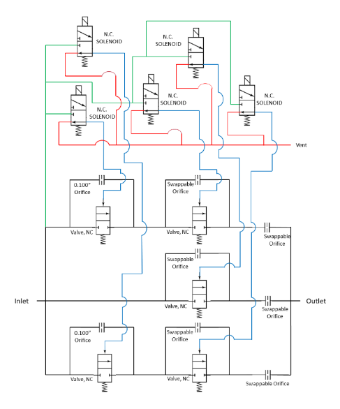
These manifolded systems control the pressurization of the fuel and oxidizer tanks. To assure reliable performance in flight, three redundant legs are part of the new design. As shown in the functional schematic in Figure 1 below, each leg contains a bypass orifice that will always allow some flow. The flow control in a single valve leg is high flow/low flow. The low flow is provided by the bypass orifice and the high flow is provided when the solenoid valve is energized and the valve opens. The ability to adjust the size of the bypass orifice during the assembly of the LV propellant system adds flexibility for the LV designer.

Figure 1: Functional Schematic

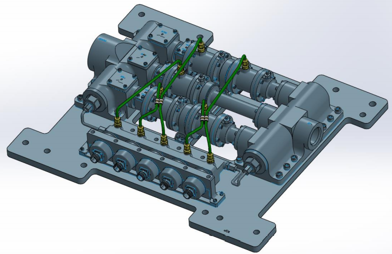
Figure 2: System Design
Designing a complex system on a tight schedule required Valcor to utilize their expertise in Model-Based Systems Engineering. The engineers had to carefully analyze the electromagnetic behavior of the solenoids, the various flow conditions for the individual legs, as well as the complete manifold, thermal behavior, structural properties of the system, and the expected behavior of the system’s response times acting under various considerations. Finite Element Models were constructed to determine structural properties of the complete system and flow behavior and were verified by manufacturing and testing a single prototype solenoid/valve combination. Custom code was utilized to determine critical thermal mismatches and considerations, as well as dynamic response time of the main valve. The digital twin and results from single valve testing helped the engineers to design a system that they are confident will aide in the construction of the entire subsystem.
Due to the challenge of designing a GNG system that was interchangeable with GOX, the propellant pressurization manifold is mostly constructed of Monel® K-500. This unique material does not burn under high pressure GOX conditions and is completely compatible with other gaseous propellants. Where Monel® could not be utilized, the engineers utilized Valcor’s extensive experience with controlling oxygen to minimize any concern about oxygen compatibility. This included minimizing direct flow impacting wetted materials that burn in high pressure oxygen environments.
The three branches provide a novel solution to the question, “What happens if a branch fails to open?” Under normal conditions, only the two outside branches operate. These outer legs each house two valves in series to regulate flow. However, all three branches have (configurable) bypass flow associated with them. As such, there will be no condition where gas is not flowing and pressurizing the propellant tanks. If one of the outer branches were to fail to open when commanded to open, the center branch can be operated to compensate for the inoperable branch.
The successful design of this system included creating custom manifolds to minimize the process connections, shrink the footprint and reduce the total weight of the system, as shown in Figure 2. Additionally, designing the branches with interchangeable bypass orifices provides the customer with the ability to tailor each system to the unique propellant requirements of each LV. Designing a propellant control system and meeting the short turnaround required by the customer was quite a challenge; one that Valcor successfully meets over and over again. How can we help you improve the performance of your fluid control application?

Recent Comments